


CO2 Laser Trouble Shooting Guide
Laser Engraver Troubleshooting: Self Support
Welcome to OMTech Laser Self Tech Support.
Got laser cutter problems? We’ve got solutions.
When your laser engraving machine doesn’t function as designed, this guide will get you back on track. For almost any technical issue, check here first for laser cutting problems and solutions.
Scroll down or press (Ctrl + F) to search for your issue by keyword. Should the expert-recommended solution not resolve your problem, use the email address located at the end of this page to send a clear description of your issue, your machine model, and previously attempted solutions. We’re here to help! Try the expert-recommended solutions. If your issue still isn’t resolved, send us an email with the details listed at the bottom of this page. We’re here to help.
To better navigate this guide, information has been simply formatted as:
- Issue Listed First
- Solutions to try are listed below.
- Additional steps to a solution will be sequentially listed.
Table of Contents
- My Laser Tube Head fell off
- My laser tube is cracked or broken
- My laser tube is leaking water into the outer chamber
- My laser tube has an Electric Arc
- My laser tube wire(s) is burnt, fried, or discolored
- My laser tube is intact, appears undamaged, but does not fire
- My laser tube only makes a weak beam
- My laser tube is making an abnormal light beam spot at Mirror #1 (i.e. donut-shaped beam spot or split beam spot)
- My laser tube’s ceramic sealing cap is damaged
- The power indicator light does not illuminate
- The level of electric current never fluctuates or hardly changes
- My power supply has an electric arc
- My laser works properly, but the ammeter/current does not change.
- My laser power is out of control or does not follow my settings
- My laser does not fire and the Laser Power Supply Display’s electrical mA current reads zero.
- My X or Y-axis gantry makes too much noise
- My laser head does not move when prompted by the control panel
- The laser head cannot move across the X or Y-axis. Or, the workbed cannot move up/down the Z-axis.
- My control panel screen does not light up
- My control panel’s display screen is blank white or flickering on/off
- The laser head will not move
- The laser head or workbed will not move across one axis, either X, Y, or Z.
- The control panel shows Error Code: Water Error or Cooler Error
- The control panel shows Error Code: “Machine Protected,” “Open Cover Protection,” or “Work Paused.”
- The control panel shows Error Code: “Jog Distance is 0, Please Reset”
- The control panel shows Error Code: “Unknown File”
- The control panel shows Error Code: “X or Y-Axis Slopover”
- The control panel shows Error Code: “Not enough extend space”
- The Low-Voltage (24V) Power Supply indicator light is off (light ON pictured below)
- Fuse blown at boot
- The control panel shows Error Code: “Machine Protected” or “Open Cover Protection Work Paused”
- The laser still fires when the workbed cover door is open
- The autofocus sensor is damaged, does not work properly, or fails to automatically focus the laser.
- The machine is unresponsive after pressing the autofocus button.
- I need to modify my autofocus parameters after I replaced/installed a new autofocus sensor.
- The red indicator light is ON.
- The green indicator light is ON and the gantry/drive motor makes noise when the axis moves.
- The green indicator light is ON and a single axis is not responsive.
- All indicator lights are OFF.
How to Restore Factory Settings
CO2 Laser Tube
1. My Laser Tube Head fell off
- Glue the laser tube head back in place with epoxy resin AB glue. Be careful to keep all glue out of the laser tube interior.
2. My laser tube is cracked or broken
- Your tube must be replaced. Take pictures that illustrate the issue and email them to techsupport@omtechlaser.com with your name, order number, laser tube number , detailed description of the issue, and any troubleshooting steps you have already taken .
My laser tube is leaking water into the outer chamber
- Your tube must be replaced. Take pictures that illustrate the issue and email them to techsupport@omtechlaser.com with your name, order number, laser tube number, detailed description of the issue, and any troubleshooting steps you have already taken.
My laser tube has an Electric Arc

- I have a YL (YongLi) laser tube with a high-pressure metal tube head:

i. Your tube must be replaced. Take pictures that illustrate the issue and email them to techsupport@omtechlaser.com with your name, order number, laser tube number, detailed description of the issue, and any troubleshooting steps you have already taken.
- I have an ERF laser tu be with a glass tube head:
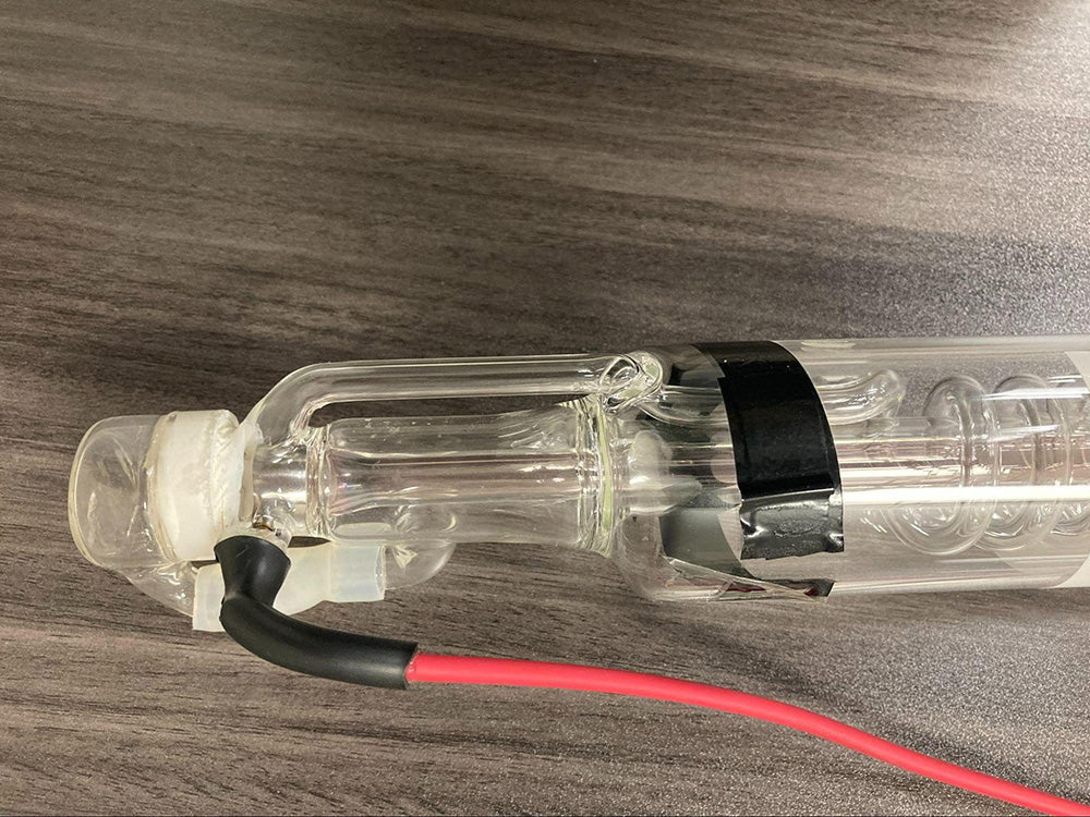
i. The red wire that connects the laser power supply to the anode, or butt-end of the laser tube, may be disconnected. You need to reseal the wire and keep it away from the metal casing of the machine. Use a blade to cut the black insulating shrink wrap off of the red wire and reconnect the wire by soldering it. Contact tech support before attempting these steps.
5. My laser tube wire(s) is burnt, fried, or discolored
You need to replace the damaged wire.
6. My laser tube is intact , appears undamaged, but does not fire
- Set laser power to 25% or above and pulse test the laser while monitoring the electric current indicated on the power supply’s mA reader.

- My mA reading goes up when I pulse my laser.
a. Your laser power supply is sending power to the laser tube, but the tube is not reacting to it. You may need to replace your laser tube, but we need more information to diagnose it. Send a video showing your issue including the laser power setting, power supply display, and working condition of the laser tube.
2. My mA reading remains the same when I pulse my laser.
a. The power supply is not working properly. Begin the troubleshooting steps under Laser Power Supply.
7. My laser tube only makes a weak beam
a. Set laser power to 25% or above and pulse test the laser again while monitoring the mA reader on the laser power supply. The mA should read within the corresponding range shown in the charts below. Then, set your laser power to 45% and repeat the process again. These steps ensure your laser power supply is delivering a consistent electrical output at various power settings.
i. My mA readings are within the specified ranges.
1. Your laser power supply is working properly, and the weak beam is caused by something else — typically dirty optics (laser mirrors or focal lens) or misaligned mirrors. First, clean your laser mirrors and focus lens by following these instructions . Second, check your laser mirror alignment by following these instructions .
ii. My mA readings are NOT within the specified ranges.
|
50W to 80W CO₂ Cabinet Lasers |
|
|
Percentage |
mA |
|
10%% |
1-3 |
|
15% |
3-4 |
|
20% |
4-6 |
|
25% |
6-8 |
|
30% |
8-10 |
|
35% |
9-11 |
|
40% |
10-12 |
|
45% |
11-13 |
|
50% |
13-15 |
|
55% |
14-16 |
|
60% |
16-19 |
|
65% |
19-21 |
|
70% |
21-24 |
|
80%+ |
22-24+ |
|
100W to 180W CO₂ Lasers |
|
|
Percentage |
mA |
|
10% |
1-3 |
|
15% |
3-4 |
|
20% |
4-6 |
|
25% |
6-8 |
|
30% |
9-11 |
|
35% |
10-13 |
|
40% |
12-14 |
|
45% |
13-15 |
|
50% |
15-18 |
|
55% |
18-22 |
|
60% |
22-25 |
|
65% |
24-28 |
|
70% |
27-30 |
|
80%+ |
28+ |
- The problem is likely in the power supply or laser tube, but we need more information to diagnose it. Send a video showing your issue including the laser power setting, power supply display, and working condition of the laser tube.
8. My laser tube is making an abnormal light beam spot at Mirror #1 (i .e. donut-shaped beam spot or split beam spot)
Abnormal laser beam spots:

Normal laser beam spot:

Set laser power to 20% and pulse test the laser again.
|
50W to 80W CO₂ Cabinet Lasers |
|
|
Percentage |
mA |
|
10%% |
1-3 |
|
15% |
3-4 |
|
20% |
4-6 |
|
25% |
6-8 |
|
30% |
8-10 |
|
35% |
9-11 |
|
40% |
10-12 |
|
45% |
11-13 |
|
50% |
13-15 |
|
55% |
14-16 |
|
60% |
16-19 |
|
65% |
19-21 |
|
70% |
21-24 |
|
80%+ |
22-24+ |
|
100W to 180W CO₂ Lasers |
|
|
Percentage |
mA |
|
10% |
1-3 |
|
15% |
3-4 |
|
20% |
4-6 |
|
25% |
6-8 |
|
30% |
9-11 |
|
35% |
10-13 |
|
40% |
12-14 |
|
45% |
13-15 |
|
50% |
15-18 |
|
55% |
18-22 |
|
60% |
22-25 |
|
65% |
24-28 |
|
70% |
27-30 |
|
80%+ |
28+ |
i. The beam spot has filled in and is back to normal.
1. Your laser tube is still working normally, but you may need to increase your laser power settings to achieve a regular beam spot.
ii. The beam spot is still abnormal.
1. Increase the laser power to 25% and repeat the procedure.
|
50W to 80W CO₂ Cabinet Lasers |
|
|
Percentage |
mA |
|
10%% |
1-3 |
|
15% |
3-4 |
|
20% |
4-6 |
|
25% |
6-8 |
|
30% |
8-10 |
|
35% |
9-11 |
|
40% |
10-12 |
|
45% |
11-13 |
|
50% |
13-15 |
|
55% |
14-16 |
|
60% |
16-19 |
|
65% |
19-21 |
|
70% |
21-24 |
|
80%+ |
22-24+ |
|
100W to 180W CO₂ Lasers |
|
|
Percentage |
mA |
|
10% |
1-3 |
|
15% |
3-4 |
|
20% |
4-6 |
|
25% |
6-8 |
|
30% |
9-11 |
|
35% |
10-13 |
|
40% |
12-14 |
|
45% |
13-15 |
|
50% |
15-18 |
|
55% |
18-22 |
|
60% |
22-25 |
|
65% |
24-28 |
|
70% |
27-30 |
|
80%+ |
28+ |
a. The beam spot has filled in and is back to normal.
i. Your laser tube is still working normally, but you may need to increase your laser power settings to achieve a regular beam spot.
b. The beam spot is still abnormal.
i. Your laser tube may need to be replaced.
11. My laser tube’s ceramic sealing cap is damaged
a. Contact us for a replacement cap and follow these video instructions to install your new ceramic sealing cap .
Laser Power Supply
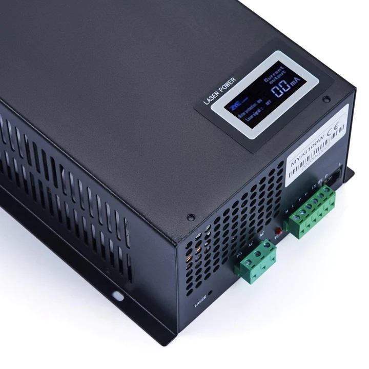
1. The power indicator light does not illuminate

a. Check the backside of the machine for an additional power cord (some larger CO₂ laser models have two power cords that must be plugged in).
i. Plug in the second power cord.
b. Ensure the emergency stop button is NOT engaged and the laser control switch (machine power switch) is in the ON position. Rotate the E-stop button clockwise to disengage it.
c. If the laser switch will not turn on, check the switch’s fuse inside the fuse box below the machine’s power plug. If burnt or broken, replace the fuse.

d. Use a multimeter to check for incoming voltage at the laser power supply’s electric input. Gently touch the two multimeter probes against each AC AC input on the green laser power supply plug. The multimeter should read about (±1)110-120V.

i. If no voltage is detected, there could be loose wiring connections. Please reinsert each of the three wires at FG, AC, and AC to ensure a proper connection.
ii. If there is voltage detected, the power supply may need to be replaced.
- The level of electric current never fluctuates or hardly changes
- Measure the electric current levels when you adjust the power to 25%, 50%, and 75%, respectively.
i. If the change in mA output is small or there is no change at all, please pull out the plug that connects the mainboard to the power supply. Then, press the TEST button on the power supply and measure the mA reading. If the reading is less than 10mA, the power supply likely requires replacement.
3. My power supply has an electric arc
a. Take a video showing the electrical arc and email it to our tech support team following the instructions at the bottom of this page. It is likely a power supply issue that may require replacement .
4. My laser works properly, but the ammeter/current does not change.
a. Please take a video showing the laser firing while the ammeter/current remains stagnant and email it to our tech support team following the instructions at the bottom of this page. Typically, your ammeter will require replacement.
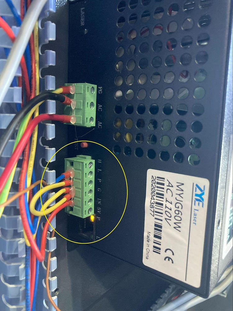
5. My laser power is out of control or does not follow my settings
a. Set your laser power setting to 1, 20, 50, and 90 respectively. After you start the laser for each setting, press the pause button on the panel and note the mA current reading on the laser power supply display.
i. My mA current reading remains the same regardless of changes in laser power setting.
Disconnect the green 6-pin plug from the laser power supply. This will disconnect the mainboard. Then press the TEST button on the power supply while monitoring the mA current output on the power supply’s display. If the current increases, the main board is faulty and may require replacement. If the current remains constant, the power supply is faulty and may require replacement.
ii. My mA current reading fluctuates along with my laser power settings as expected.
1. Your power control seems to function fine.
6. My laser does not fire and the Laser Power Supply Display’s electrical mA current reads zero.
- Set your laser power setting to 1, 20, 50, and 90 respectively. After you start the laser for each setting, press the pause button on the panel and note the mA current displayed on the laser power supply.
i. My mA current reading remains the same regardless of changes in the laser power setting.
1. Disconnect the green 6-pin plug from the laser power supply. This will disconnect the mainboard. Then press the TEST button on the power supply while monitoring the mA current output on the power supply’s display. If the current increases, the main board is faulty. If the current remains constant, the power supply is faulty and may require replacement.
ii. My mA current reading fluctuates along with my laser power settings as expected.
Your power control seems to function fine.
b. My laser will not fire or pulse at all.
i. Locate your laser power supply and disconnect the green 6-pin plug.
Then, press the small red TEST button to test fire the laser while monitoring the mA current reading.
1. My laser still does not fire using the TEST button
2. My laser did fire using the TEST button and the output was greater than 10 mA.
The problem is likely your control panel. Scroll down to the Control Panel troubleshooting steps.[a]
3. My laser did fire using the TEST button but the output was less than 10 mA.
- The problem is likely your laser power supply, but we need more information to help you.
Motors and Drives
- My X or Y-axis gantry makes too much noise
- Jog the laser head to the center of the workbed. Turn the machine off and then back on while observing when the noise occurs.
i. If the noise occurs immediately after you turn on the machine, open the control box and check the drive’s indicator lights.

- If the green light is on: The driver should be fine, but the problem may be in the motor or wiring.
- If one axis moves smoothly, but the other does not, swap the motor plugs on the faulty drive and the working drive, then restart. The two green 4-plug terminal block connectors are labeled Signal (5V).

i. Listen for the noise again, it should be transferred to the other axis. If so, switch the motor plugs back to their original position. Then, swap the drive plugs on the mainboard; they are two 3-plug terminal block connectors located on the top left of the mainboard, labeled Axis Y & Axis X.

- If the noise is transferred to the other axis, you will need to replace the mainboard.
2. If the noise is not transferred to the other axis, you will need to replace the drive .
b. If it does not move smoothly, locate the impediment and inspect the gantry for debris, bends, or other “stuck” mechanisms. You may need to clean and lubricate the entire gantry.
ii. If the noise occurs after the laser head moves to the origin, check whether the limit switches are being triggered. Jog the laser head until it touches each of the two limit switches. You should see a red light on the limit switches flash, indicating they are working properly.

- If the red light does not flash, move the laser head out of the way and place a small metal item on the limit switch. It should flash a red light indicating it is working.

- If the red light flashes for your metal item but not the laser head, you simply need to adjust the height of the limit switch so it barely touches the laser head.
- If the red light does not flash, even for the metal item, please contact us about replacing the limit switch with your name & order number. VIDEO INSTRUCTIONS: How to Replace Your Limit Switch
2. My laser head does not move when prompted by the control panel
- Check the limit switches’ red indicator lights
i.Indicator light is always on
1. Check for any metal items or parts touching the limit switch and remove them. If there is no metal, the limit switch needs replacement. VIDEO INSTRUCTIONS: How to Replace Your Limit Switch
ii. Indicator light is off
2. Place a small metal item on the limit switch to test it. The red indicator light should flash. If not, the limit switch needs replacement. VIDEO INSTRUCTIONS: How to Replace Your Limit Switch
- Check for an error code on the control panel
i. If error code “Jog Distance is 0, please reset” appears, press the “Jog/Continuous” button on the control panel.
ii. If no error code appears, connect the machine to your computer and attempt to jog the laser head using your laser software.
1. If the laser head does move using your software, the control panel is faulty and may require replacement.
2. If your software cannot move the laser head, you may need to restore the factory settings on the control panel. If your machine has the Ryzon KT332N, you can restore factory settings immediately using the password RT6666 or HF8888. However, if your machine has the Ruida RDC6442Gbec, please call tech support before resetting the mainboard, as we can help restore the parameters immediately following your reset. After the factory reset, move the laser head to the center of the workbed and then turn the machine back on.
a. If the machine resets normally, but the software and control panel still cannot move the laser head, the mainboard is likely faulty.
If the laser head does not rehome to the origin upon startup, scroll down to the Drive Troubleshooting Instructions: Single or Double Axis Failure[b]
3. The laser head cannot move across the X or Y-axis. Or, the workbed cannot move up/down the Z-axis.
a. Turn the power off and attempt to move the problematic axis by hand.
i. If it cannot move by hand, check whether the gantry or Z-axis belt drive is stuck due to debris, physical damage, or other impediments.
ii. If it can move by hand:
- Check for loose set screws on the motor pulley and tighten them.
- Check if the axis drive belt is loose or off-track. Adjust the drive belt back on the track. If the belt tension is loose, locate the tightening screws on the front-right side of the machine (where the right side Y-axis gantry meets the front metal frame) and tighten the belt by equally rotating both screws clockwise 1-3 turns (or more if necessary) with an Allen key.


- If the motor still cannot move the specific axis, but it does move by hand, the motor likely needs to be replaced. Contact us for more information.
- Check the limit switches’ red indicator lights
i. Indicator light is always on
- Check for any metal items or parts touching the limit switch and remove them. If there is no metal, the limit switch needs replacement.
ii. Indicator light is off
- Place a small metal item on the limit switch to test it. The red indicator light should flash. If not, the limit switch needs replacement .
c. Connect the machine to your computer and attempt to jog the laser head using your laser software.
i. If the laser head does move using your software, the control panel is faulty and may require replacement.
ii. If your software cannot move the laser head, you may need to restore the factory settings on the control panel. If your machine has the Ryzon KT332N mainboard, you can restore factory settings immediately using the password RT6666 or HF8888. However, if your machine has the Ruida RDC6442Gbec mainboard, please call tech support before resetting the mainboard, as we can help restore the parameters immediately following your re set. After the factory reset, move the laser head to the center of the workbed, turn the machine back on, and attempt to move the laser head with your software again.
- If the problem persists, Check the Drive Instructions (single axis failure)
d. Check the drive indicator lights
i. Red indicator light is on
1. Unplug the power plug on the motherboard and use a multimeter to measure the voltage coming through the faulty driver at the green 2-plug terminal block connector located on the right side of the driver, labeled GND & VDC. It should read (±1)24V.
- The voltage measured does not read (±1)24V.
i. The low-voltage power supply may be faulty.
- The voltage measured reads (±1)24V.
i. Swap the motor plugs on the faulty drive and the normal drive. The green 4-plug terminal block connector is located on the right side of each driver, labeled Motor. Then, test the machine again.

- The fault was transferred to the other drive.
a. The motor is likely defective. Please contact us for more information.
2. The fault was not transferred: turn off the machine and swap the motor plugs back to their original position. Then, swap the drive plugs on the motherboard; they are two 3-plug terminal block connectors located on the top left of the mainboard, labeled Axis Y & Axis X.
- The fault was transferred to the other drive.
i. The motherboard is likely defective.
b. The fault was not transferred to the other drive.
i. The drive is likely defective.
ii. Green indicator light is on
1. Swap the motor plugs on the faulty drive and the normal drive. The green 4-plug terminal block connector is located on the right side of each driver, labeled Motor. Then, test the machine again.
a. The fault was not transferred to the other drive.
i. The motor is likely defective. Contact us for more information.
b. The fault was transferred to the other drive.
i. Swap the motor plugs back to their original position. Then, swap the drive plugs on the motherboard. The two 3-plug terminal block connectors are located on the top left of the mainboard, labeled Axis Y & Axis X.
b. The fault was transferred to the other drive.
i. The motherboard is likely defective.
2. The fault was not transferred to the other drive.
a. The drive is likely defective.
iii. Both indicator lights are off
1. The driver may not be receiving any power from the low-voltage power supply. Measure the input and output voltage of the low-voltage power supply using a multimeter. The input voltage should read about (±1)120V and the output voltage should read (±1)24V.


a. The input voltage measured is (±1)120V and the output voltage measured is (±1)24V.
i. The drive is likely defective.
b. The voltage measured is not (±1)120V input and (±1)24V output.
i. The low-voltage power supply is likely defective.
Control Panel
- My control panel screen does not light up
Check whether the control switch lights up. Depending on your laser model, the control switch may be on the right side of the machine or the top right, as seen below:

i. Control switch indicator light is OFF
- First, make sure the emergency switch is turned off. Once pressed down, it remains in the down position until lifted up. Then, check the wiring from the E-stop to the power supply for loose connections. The wires may slip out of the green terminal block connectors, but can simply be reinserted. Then, check the back of the control switch socket for loose wiring, and ensure all four wires are completely inserted.
- If the laser power supply does not power on, also check if the fuse is burnt, and use the replacement fuse if necessary.
ii. Control Switch indicator light is ON
- Check whether the low-voltage (24v) power supply indicator light is ON or OFF (ON pictured below).

- Power supply indicator light is OFF
i. The low-voltage power supply likely needs to be replaced. Contact us for more information.
- Power supply indicator light is ON
i. Use a multimeter to measure the mainboard input voltage, connecting your two probes to the green two-plug terminal connectors at the bottom center of the mainboard, labeled GND & 24V. Your reading should be (±1)24V.

- The mainboard input voltage measured is (±1)24V.
- The control panel must be replaced. Contact us for more information.
2. The mainboard input voltage measured does not read (±1)24V.
- Unplug the mainboard’s power input and measure the plug’s voltage. It should read (±1)24V.

i. If the mainboard input voltage reads (±1)24V, the mainboard needs to be replaced.
ii. If the mainboard input voltage does not read (±1)24V, the low-voltage power supply needs to be replaced.
2. My control panel’s display screen is blank white or flickering on/off
- Disconnect and reconnect the control panel from the motherboard by unplugging the white terminal block connector on the motherboard labeled HMI, as seen below.

- If it still doesn’t work properly, your control panel must be replaced. Contact us for more information.
3. The laser head will not move
- the laser head will not move and an error code on the display reads, “jog distance is 0, please reset.”
i. Press the control panel button in the center of the arrow keys to change the Jog/Continuous setting.
- The laser head will not move and there is no error code on the display.
i. The control panel does not make a beeping sound when you press the arrow keys.
1. Your control panel may need to be replaced, but we need more information to determine this. Please contact us for more information.
ii. You may need to restore the factory settings on the control panel. If your machine has the Ryzon KT332N mainboard, you can restore factory settings immediately using the password RT6666 or HF8888. However, if your machine has the Ruida RDC6442Gbec mainboard, please call tech support before resetting the mainboard, as we can help restore the parameters immediately following your reset. After the factory reset, move the laser head to the center of the workbed, turn the machine back on, and attempt to move the laser head with your software again.
- If the laser head still won’t move, attempt to move it using your laser software.
a. If the software controls can move the laser head, but the control panel cannot, your control panel must be replaced. Please contact us for more information.
b. If the software controls still cannot move the laser head, begin the Drive Troubleshooting Instructions
4. The laser head or workbed will not move across one axis, either X, Y, or Z.
a. My laser head will move across the axis in question, but not all the way across.
i. Enter your laser software and ensure your machine and computer are connected via a USB cable.
In LIGHTBURN: Open LightBurn, click on Edit and open Machine Settings. Scroll down and click on Vendor Settings, then click YES for the popup warning. Scroll further down to the X, Y, or Z Axis Settings (depending on your faulty axis) and ensure the Max Travel setting is correctly set up for your workbed size, see chart below.
RDWORKS: Open RDWorks, click on File, Vendor Settings. Enter the password RD8888. Click Read in the popup window, then ensure the Breadth setting matches your workbed size.
|
Model |
Max. Travel Setting |
|
MF1220-50 |
300×500 |
|
MF1220-50R |
300×500 |
|
USB-5G3R-DE |
300×505 |
|
MF1624-55 |
400×600 |
|
AF1630-70 |
400×750 |
|
MF1630-70 |
400×750 |
|
ZF1630-70 |
400×750 |
|
MF2028-60 |
500×700 |
|
AF2028-60 |
500×700 |
|
ZF2028-60 |
500×700 |
|
AF2028-80 |
500×700 |
|
MF2028-80 |
500×700 |
|
ZF2028-80 |
500×700 |
|
MF2028-100 |
500×700 |
|
AF2028-100 |
500×700 |
|
ZF2028-100 |
500×700 |
|
AF2435-80 |
600×900 |
|
ZF2435-80 |
600×900 |
|
AF2435-100 |
600×900 |
|
ZF2435-100 |
600×900 |
|
ZF2436-80 |
650×900 |
|
MF2440-80 |
1000×600 |
|
AF2440-80 |
1000×600 |
|
ZF2440-80 |
1000×600 |
|
MF2440-100 |
1000×600 |
|
AF2440-100 |
1000×600 |
|
ZF2440-100 |
1000×600 |
|
ZF3551-100 |
1300×900 |
|
AF3551-130 |
1300×900 |
|
ZF3551-130 |
1300×900 |
|
AF3555-130 |
1400×900 |
|
ZF3555-130 |
1400×900 |
|
AF4063-150 |
1600×1000 |
|
ZF4063-150 |
1600×1000 |
|
AF5070-150 |
1800×1300 |
- You may need to restore the factory settings on the control panel. If your machine has the Ryzon KT332N mainboard, you can restore factory settings immediately using the password RT6666 or HF8888. However, if your machine has the Ruida RDC6442Gbec mainboard, please call tech support before resetting the mainboard, as we can help restore the parameters immediately following your reset. After the factory reset, move the laser head to the center of the workbed, turn the machine back on, and attempt to move the laser head with your software again.
a. If the axis still won’t work after restoring factory control panel settings, attempt to use the axis by moving the laser head or workbed in your laser software controls.
- If the software controls can move the laser head across the axis in question, but the control panel cannot, your control panel must be replaced. Please contact us for more information.
- If the axis in question still won’t work using the software controls, begin the Motor and Drive Troubleshooting instructions.
5. The control panel shows Error Code: Water Error or Cooler Error
a. These Error Codes refer to the Water Cooling System. Check the configuration and flow direction of the water cooling system. Check the water hoses and connection points for leaks. The water pump/chiller OUTLET must be connected to the laser tube INLET.
b. Check the water cooling system for adequate water flow. Disconnect the water pump/chiller outlet and check for normal water flow. Check for kinks in the hoses. Correct any water flow issues or replace the water pump/chiller if necessary.
c. Ensure the four bolts holding the water flow sensor in place are facing upwards, otherwise, you need to adjust the installation angle.
i. If you complete all three steps above, and the Water/Cooler Error code persists, the Water Flow Sensor needs to be replaced. Contact us for a replacement. In the meantime, you can bypass the water flow sensor using your laser software settings.
In LIGHTBURN: Open LightBurn, click on Edit, Machine Settings, double click on Vendor Settings, Scroll down to Water Protect Enable, Laser 1, and switch this setting to FALSE. Then click Write to save the change. Now, pulse test laser to ensure it can fire.
In RDWORKS: Open RDWorks, click File, Vendor Settings, enter password RD8888, click on the Laser tab, scroll down to Water Protect and uncheck the corresponding box. Click Write to save the change. Now, pulse test the laser to ensure it can fire.
- The Water/Cooler Error code stops after disabling the water flow sensor.
a. The water flow sensor needs to be replaced.
- The Water/Cooler Error persists after disabling the water flow sensor in my laser software.
a. Your laser software may have failed to write the setting change. Check your Water Protect setting again in LightBurn or RDWorks.
i. The Water/Cooler Error persists after disabling the water flow sensor in my laser software.
- Short-circuit the water flow sensor interface on the main board by removing the two water protection wires labeled WP1 and L-0n1 in the CN5 terminal on the left side of the mainboard. Remove the two wires and splice them together.

- The Water/Cooler Error persists after short-circuiting the mainboard water flow sensor interface.
i. Contact us for more information
6. The control panel shows Error Code: “Machine Protected,” “Open Cover Protection,” or “Work Paused.”
- These error codes refer to the Workbed Door Sensor. Open the workbed cover door and locate the door sensor on either the right or left side of the door jam.

- Place a magnet on the door sensor and check if the Error Code stops.
i. The Error Code stops once the magnet is placed on the door sensor.
1. The door sensor still works, it just needs to be repositioned so that the door touches it when closed. Adjust the door sensor by hand and close the door to test it.
ii. The Error Code persists after the magnet is placed on the door sensor.
1. The door sensor does not work and must be replaced.
7. The control panel shows Error Code: “Jog Distance is 0, Please Reset”
- Your control panel is in Manual movement mode, but your Jog Distance setting is 0. To use the Continuous movement mode instead, press Escape, then press Jog/Continuous button on the control panel (the center directional button).
8. The control panel shows Error Code: “Unknown File”
- You may need to update your laser software. Use the latest version of RDWorks to upgrade the machine’s mainboard.
9. The control panel shows Error Code: “X or Y-Axis Slopover”
- This means the locating position is too close to the edge, or the graphic is too large. Move the origin of the project or shrink your graphic to fit using your control panel or laser software. Then, frame the project again.
10. The control panel shows Error Code: “Not enough extend space”
- The graphic file is just small enough to fit within the workbed parameters, but there is no edge space for the laser head to slow down and reverse. Modify or shrink the file to fit within the workbed parameters leaving more space around the edges of the graphic.
Low-Voltage Power Supply
- The Low-Voltage (24V) Power Supply indicator light is off (light ON pictured below)
- Measure the power supply’s AC input voltage using a multimeter at the terminal blocks
labeled (AC) L & N. It should read (±1)120V.

i. The power supply’s input voltage is at or near a normal level of (±1)120V.
- The power supply must be replaced.
ii. The power supply’s input has no voltage measured.
- The input power is not reaching the low voltage power supply, and you must find where the cutoff is occurring. First, make sure the emergency switch is turned off (Once pressed down, it remains in the down position until lifted up). Then, check the wiring from the back of the E-stop to the power supply for loose connections. The wires may slip out of the green terminal block connectors, but can simply be reinserted. Next, check the back of the control switch socket for loose wiring, and ensure all four wires are completely inserted.

Finally, check if the fuse is burnt, and use the replacement fuse if necessary.
- Fuse blown at boot
a. Replace the blown fuse with the provided replacement.
Mainboard

Light is off
- Check whether the low-voltage power supply light is on.
i. the low-voltage power supply light is on
- Measure the mainboard input voltage with a multimeter. It should read (±1)24V.
- Mainboard input voltage reads (±1)24V.
i. The mainboard must be replaced.
b. The mainboard input voltage does not read (±1)24V.
i. The low-voltage power supply must be replaced.
ii. The low-voltage power supply light is off
- The input power is not reaching the low voltage power supply, and you must find where it is cut off. First, make sure the emergency switch is turned off. Once pressed down, it remains in the down position until lifted up. Then, check the wiring from the E-stop to the power supply for loose connections. The wires may slip out of the green terminal block connectors, but can simply be reinserted. Then, check the back of the control switch socket for loose wiring, and ensure all four wires are completely inserted.

Finally, check if the fuse is burnt, and use the replacement fuse if necessary.
Water Flow Sensor
- Water Leakage
- Locate the water leak and plug the leak by either reinstalling the gasket or using waterproof tape (teflon or plumber’s tape) to seal the leaky hose. (reference video 6).
2. The control panel shows Error Code: “Water Error” or “Cooler Error”
- These Error Codes refer to the Water Cooling System. Check the configuration and flow direction of the water cooling system. Check the water hoses and connection points for leaks. The water pump/chiller OUTLET must be connected to the laser tube INLET.
- Check the water cooling system for adequate water flow. Disconnect the water pump/chiller outlet and check for normal water flow. Check for kinks in the hoses. Correct any water flow issues or replace the water pump/chiller if necessary.
- Ensure the four bolts holding the water flow sensor in place are facing upwards, otherwise you need to adjust the installation angle.
i. If you complete all three steps above, and the Water/Cooler Error code persists, the Water Flow Sensor needs to be replaced. Contact us for a replacement. In the meantime, you can bypass the water flow sensor using your laser software settings.
In LIGHTBURN: Open LightBurn, click on Edit, Machine Settings, double click on Vendor Settings, Scroll down to Water Protect Enable, Laser 1, and switch this setting to FALSE. Then click Write to save the change. Now, pulse test laser to ensure it can fire.
In RDWORKS: Open RDWorks, click File, Vendor Settings, enter password RD8888, click on the Laser tab, scroll down to Water Protect and uncheck the corresponding box. Click Write to save the change. Now, pulse test the laser to ensure it can fire.
1. The Water/Cooler Error code stops after disabling the water flow sensor.
- The water flow sensor needs to be replaced.
2. The Water/Cooler Error persists after disabling the water flow sensor in my laser software.
- Your laser software may have failed to write the setting change. Check your Water Protect setting again in LightBurn or RDWorks..
- The Water/Cooler Error persists after disabling the water flow sensor in my laser software.
i. Short circuit the water flow sensor interface on the main board by removing the two water protection wires labeled WP1 and L-0n1 in the CN5 terminal on the left side of the mainboard. Remove the two wires and splice them together.
- The Water/Cooler Error persists after short-circuiting the mainboard water flow sensor interface. Contact us for more information.
Air Pump
- The air pump is not working and does not make a sound.
- The air pump must be replaced.
2. The air pump makes noise but has no airflow.
- First, check the pump for clogs. Then, disassemble and clean the pump, ensuring all debris is removed. 1. Then, test the air pump again.
i. The clean air pump still does not provide airflow.
- The air pump must be replaced.
Open Cover Protection
- The control panel shows Error Code: “Machine Protected” or “Open Cover Protection Work Paused”
- Locate the door sensor on either the right or left side of the workbed cover door jam, and place a magnet directly on the door sensor.

i. The Open Cover Protection’s indicator light turns on.
- The Door Sensor is still working, and may be contacting metal even when the workbed cover door is closed. Adjust the position of the door sensor so that it touches the door’s metal jam only when clos ed.
ii. The Open Cover Protection’s indicator light does not turn on.
- The Door Sensor must be replaced.
The laser still fires when the workbed cover door is open
- Locate the door sensor on either the right or left side of the workbed cover door jam, and place a magnet directly on the door sensor.
i. The Open Cover Protection’s indicator light turns on
- The Door Sensor is still working, but the workbed cover door is not touching the sensor when closed. Adjust the position of the door sensor so that it touches the door’s metal jam when closed.
ii. The Open Cover Protection’s red indicator light does not turn on.
- The Door Sensor must be replaced.
b. Check whether the machine settings in the software are correct.
In LIGHTBURN: Open LightBurn, click on Edit, Machine Settings, scroll down and double click Vendor Settings, scroll down to Enable Door Open Protect and switch this setting to False. Then, pulse test the laser to ensure it fires.
In RDWORKS: Open RDWorks, click on File, Vendor Settings, enter password RD8888, click on the Other tab, locate Enable Protect and uncheck the box to disable this setting. Click Write to save the change. Then, pulse test the laser to ensure it fires.
Proximity/ Limit Switches
- The laser head does not home properly upon startup.
The laser head is crashing into the side of the workbed.
The limit switches are not being triggered.
- Check whether the limit switches are being triggered. Jog the laser head until it touches each of the two limit switches. You should see a red light on the limit switches flash, indicating they are working properly.
- If the red light does not flash, move the laser head out of the way and place a small metal item on the limit switch. It should flash a red light indicating it is working.
- If the red light flashes for your metal item but not the laser head, you simply need to adjust the height of the limit switch so it barely touches the laser head.
- If the red light does not flash, even for the metal item, please contact us about replacing the limit switch with your name & order number. VIDEO INSTRUCTIONS: How to Replace Your Limit Switch
Laser Mirrors
- The laser mirror(s) are dirty.
- Clean the mirrors thoroughly with a cotton pad or microfiber cloth dipped in isopropyl alcohol.
i. The mirror is still dirty, scratched, or otherwise damaged after cleaning.
- The mirror must be replaced.
- The mirror has silicone on the bolts
- Silicone is placed on the reflector during manufacturing to prevent shifting during the shipping process. You can simply wipe it away.
Focus Lens
- My focus lens is dirty
- Clean the focus lens thoroughly with a cotton pad or microfiber cloth dipped in isopropyl alcohol.
- The focus lens is still dirty, scratched, or otherwise damaged after cleaning.
i. The focus lens must be replaced. VIDEO INSTRUCTIONS: How to Replace Your CO2 Laser Focus Lens
- The focus lens must be replaced. VIDEO INSTRUCTIONS: How to Replace Your CO2 Laser Focus Lens
Water Pump
- The water pump is not circulating water properly.
- The water pump must be replaced.
Autofocus Sensor
- The autofocus sensor is damaged, does not work properly, or fails to automatically focus the laser.
- Manually press up on the tip of the red sensor. A red indicator light on top of the sensor should flash on.
i. The red indicator light is ON.
1. The control panel may not be configured correctly for autofocus. Restore factory settings using the password RT6666 or HF8888, then test the autofocus again.
- My autofocus still does not work after restoring factory settings.
i. Check the drive (single axis)
ii. The red indicator light is OFF.
- The autofocus pen must be replaced.
- The machine is unresponsive after pressing the autofocus button.
- The control panel also shows Error Code: Jog distance is 0, please reset.
i. Press the "Jog/Continuous" button on the panel under the initial interface (the button in the middle of the UP, DOWN, LEFT, and RIGHT buttons).
- The control panel does not show any Error Code.
i. Restore factory settings using the password RT6666 or HF8888, then test the autofocus again.
- My autofocus still does not work correctly.
- Connect the machine to your computer’s laser software and attempt to move the workbed (Z-Axis) up and down in the software.
i. The workbed does move up/down using laser software.
- The control panel is faulty and must be replaced.
i. The workbed does NOT move up/down using laser software.
- Check the drive (multi-axis)
3. I need to modify my autofocus parameters after I replaced/installed a new autofocus sensor.
- Option 1:
i. Enter the “factory settings” in the software with password RD8888
ii. Select Z-or U-axis settings (determined by the panel)
iii. Check the origin offset
iV. Press auto focus
v. Manually adjust the focus (with the machine turned on)
vi. Check the Z-or U-axis coordinates on the control panel
vii. Do a calculation of adding this coordinate to the previous origin offset data
viii. Refill the result and save.
b. Option 2: Adjust the height of the autofocus pen.
Drive - Single Axis Failure
1. The red indicator light is ON.
a. Swap the motor plugs on the faulty drive and the normal drive. The green 4-plug terminal block connector is located on the right side of each driver, labeled Motor. Then, test the machine again.
i. The fault was not transferred to the other drive.
1. The drive motor needs to be replaced.
ii. The fault was transferred to the other drive.
1. Switch the motor plugs back to their original position, then swap the drive plugs on the mainboard. They are two 3-plug terminal block connectors located on the top left of the mainboard, labeled Axis Y & Axis X.
a. The fault was not transferred to the other drive.
i. The motor drive needs to be replaced.
b. The fault was transferred to the other drive.
i. The mainboard needs to be replaced.
2. The green indicator light is ON and the gantry/drive motor makes noise when the axis moves.
a. Attempt to move the faulty axis by hand to check for smooth movements.
i. The faulty axis does move smoothly.
1. Swap the motor plugs on the faulty drive and the working drive. The green 4-plug terminal block connector is located on the right side of each driver, labeled Motor. Then, test the machine again.
a. The fault was not transferred to the other drive.
i. The drive motor needs to be replaced.
b. The fault was transferred to the other drive.
i. Switch the motor plugs back to their original position, then swap the drive plugs on the mainboard. The two 3-plug terminal block connectors are located on the top left of the mainboard, labeled Axis Y & Axis X.
1. The fault was not transferred to the other drive.
a. The motor drive needs to be replaced.
2. The fault was transferred to the other drive.
a. The mainboard needs to be replaced.
ii. The faulty axis does not move smoothly.
1. The axis may be “stuck” on a physical obstruction. Closely examine the axis’s rails and other moving parts for debris that may be impeding its movement.
3. The green indicator light is ON and a single axis is not responsive.
a. Swap the motor plugs on the faulty drive and the working drive The green 4-plug terminal block connector is located on the right side of each driver, labeled Motor. Then, test the machine again.
i. The fault was not transferred to the other drive.
1. The drive motor needs to be replaced.
ii. The fault was transferred to the other drive.
1. Switch the motor plugs back to their original position, then swap the drive plugs on the mainboard. They are two 3-plug terminal block connectors located on the top left of the mainboard, labeled Axis Y & Axis X.
a. The fault was not transferred to the other drive.
i. The motor drive needs to be replaced.
b. The fault was transferred to the other drive.
i. The mainboard needs to be replaced.
4. All indicator lights are OFF.
a. Unplug the power plug on the motherboard and use a multimeter to measure the voltage coming through the faulty driver at the green 2-plug terminal block connector located on the right side of the driver, labeled GND & VDC. It should read (±1)24V.

i. The voltage measured does not read(±1)24V.
1. The low-voltage power supply may be faulty.
ii. The voltage measured reads (±1)24V.
- Swap the motor plugs on the faulty drive and the normal drive. The green 4-plug terminal block connector is located on the right side of each driver, labeled Motor. Then, test the machine again.
a. The fault was transferred to the other drive.
i. The motor is likely defective. Please contact us for a replacement.
b. The fault was not transferred: turn off the machine and swap the motor plugs back to their original position. Then, swap the drive plugs on the motherboard; they are two 3-plug terminal block connectors located on the top left of the mainboard, labeled Axis Y & Axis X.
i. The fault was transferred to the other drive.
1. The motherboard is likely defective.
ii. The fault was not transferred to the other drive.
1. The drive is likely defective.
b. Use a multimeter to measure the low-voltage power supply’s input voltage at terminal connectors labeled (AC) L & N. It should read (±1)120V.
i. The measured voltage is (±1)120V.
1. The drive must be replaced.
ii. The measured voltage is NOT (±1)120V.
1. The low voltage power supply must be replaced.
Drive - Multiple Axis Failure
The red indicator lights are ON for all drives
a. Unplug the mainboard’s power input and use a multimeter to measure the plug’s voltage. It should read (±1)24V.
i. The measured voltage is NOT (±1)24V.
1. There is likely a problem with the low-voltage power supply.
ii. The measured voltage is (±1)24V..
1. Restart the machine. Then, check the drive’s indicator lights.
a. The red indicator light is ON for only 1 drive.
i. Swap the motor plugs on the faulty drive and the working drive. The green 4-plug terminal block connector is located on the right side of each driver, labeled Motor. Then, test the machine again.
1. The fault was not transferred to the other drive.
a. The drive motor needs to be replaced.
2. The fault was transferred to the other drive.
a. Switch the motor plugs back to their original position, then swap the drive plugs on the mainboard. They are two 3-plug terminal block connectors located on the top left of the mainboard, labeled Axis Y & Axis X.
i. The fault was not transferred to the other drive. The motor drive needs to be replaced.
ii. The fault was transferred to the other drive. The mainboard needs to be replaced.
b. The red indicator light is ON for 2 drives.
i. The problem likely stems from faulty wiring or the mainboard. Turn off the entire machine and unplug both drivers from the mainboard. The two 3-plug terminal block connectors are located on the top left of the mainboard, labeled Axis Y & Axis X.
1. Then, turn the machine back on while monitoring the driver indicator lights.
a. Green indicator lights are ON
The drivers are working fine, but the problem likely stems from the motherboard.
2. The red indicator lights are ON.
a. The problem is caused by the drivers or by faulty wiring between the drivers and their motors.
2. The faulty axis’s green indicator light is ON.
a. Swap the motor plugs on the faulty drive and the working drive. The green 4-plug terminal block connector is located on the right side of each driver, labeled Motor. Then, test the machine again. The fault may transfer to the new axis.
i. The fault was transferred to the other axis.
1. The driver motor is likely faulty.
ii. The fault was NOT transferred to the other drive.
1. The original driver is likely faulty. Swap the motor plugs back to their original position and contact us for more information.
How to Restore Factory Settings
There are three different Mainboard models in OMTech CO₂ laser machines. Open the side access panel and identify your mainboard model. Before you reset your control panel to factory settings, please contact us as the factory reset can sometimes cause adverse effects.
Mainboard Model: RDC6442/RDC6445, Password: HF8888
Mainboard Model: KT332N, Password: RT6666
Software Issues
Please call or email tech support for software issues within RDWorks.
Contact Tech Support
Take pictures that illustrate the issue and email them to techsupport@omtechlaser.com with your name, order number, laser tube number, detailed description of the issue, and any troubleshooting steps you have already taken.
Limit/Proximity Switches – Sensors located at the end of the X & Y gantry rails that detect the location of the laser head by sensing its metal components. The two sensors prevent the laser head from trying to move beyond the workbed limits and relay the laser head’s location to the control panel.
Focal/Focus Lens – A transparent lens inside the laser head that transmits the raw laser beam on a path of convergence, focusing the beam’s light energy into a smaller point so it can cut or engrave.


Laser Mirrors – A set of three mirrors mounted inside the machine that reflect and direct the CO₂ laser beam along its path from the laser tube, through the focal lens, and onto the target material.


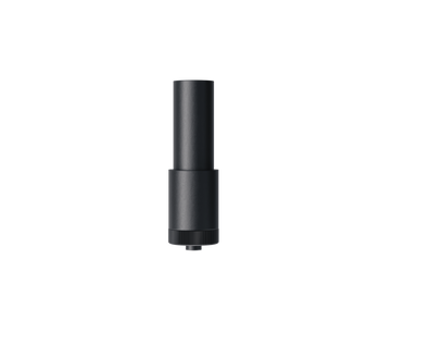
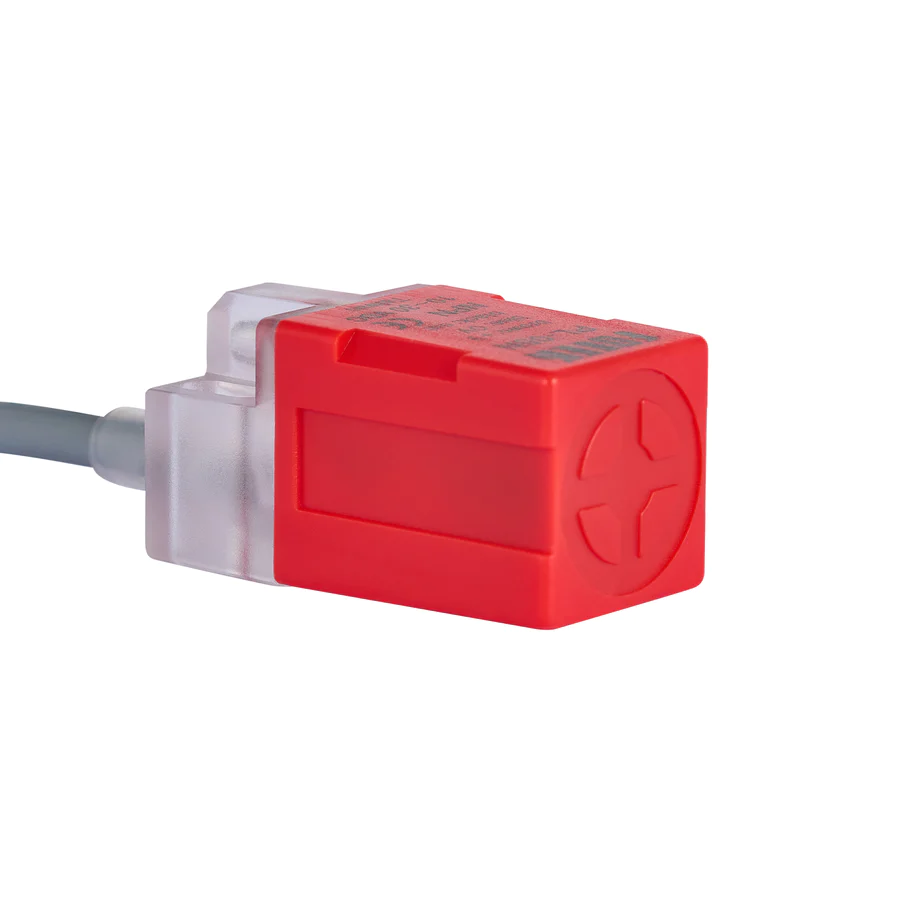
Autofocus Sensor – The red plunger-style sensor attached to the laser head that senses the target material’s position to help adjust the workbed to the perfect laser focus height.

Motor Plugs – The terminal block and wiring that connect the drivers to their motors which power the gantry movements.
X-Axis & Y-Axis – These terms refer to the workbed and the gantry rails that move the laser head. The X-axis runs from left to right along the width of the workbed, while the Y-axis runs from front to back along the depth of the workbed.
Z-Axis – This refers to the adjustable height of their workbed. The Z-axis denotes up and down movement that allows the workbed to accommodate items of various sizes.
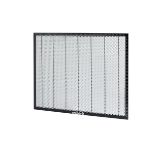
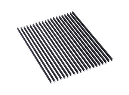
Workbed – The main rectangular surface inside the machine cabinet on which your target material rests. Typically made of a honeycomb-style metal that allows the excess laser light to pass through and dissipate, preventing laser beam reflections.
Drive – The motors and drivers that power and control the gantry movements. There is one driver and one motor for each movable axis.


Drive Belt – The belt that transmits power from the drive motors to the gantry, making it move in various directions specified by the drivers.
Laser Head – The metal tube mounted on the X-axis gantry rail that houses the third laser mirror and focal lens. The focused laser beam emerges from the tip of the laser head before striking the target material.

Jog – Moving the laser head around the workbed using the control panel directional keys.
Electric Arc – When the laser tube produces a rogue beam of electricity that does not fire towards the first mirror, but towards the nearest metal component.
Water Cooling System – The system that cools the laser tube by pumping water through a water cooling jacket that surrounds the CO₂ laser tube’s internal chamber where the laser beam originates. This system can include a refrigeration system called a laser water chiller or simply a pump with a reservoir of cool water.
Water Flow Sensor – This unit senses the flow of water through a hose that leads directly to the CO₂ laser tube. It protects the laser tube from heat damage by preventing the laser tube from firing when water flow is not detected.
Mainboard – The central communication hub between various electronic elements of the laser engraving system, including the laser power supply, control panel, drivers, limit switches, etc.
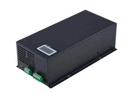
110/120V/High-Voltage Laser Power Supply – The secondary electric powerhouse that supplies the laser tube with amplified electricity to create laser beams.
24V/Low-Voltage Power Supply – The primary electricity hub that supplies basic power to various electronic elements of the laser engraving system, including the red dot pointer, control panel, mainboard, drivers, etc.
Multimeter – A electricity sensing device that allows you to measure the amount of AC and DC current running through a particular device.